Sequence diagrams and use case diagrams are often taught together because they sit at different levels of the same design conversation. One shows how objects talk to each other over time; the other shows what an outside user can expect the system to do. They are not interchangeable, and neither is self-explanatory just because the symbols look simple.
Sequence diagrams
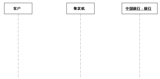
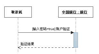
A sequence diagram is mainly about order. It presents an interaction as a two-dimensional drawing: time runs down the vertical axis, and the horizontal axis holds the roles of the independent objects taking part in the collaboration. Each role is drawn as a lifeline. While the object exists, the role is a dashed line; while its process is active, the lifeline becomes a double line.
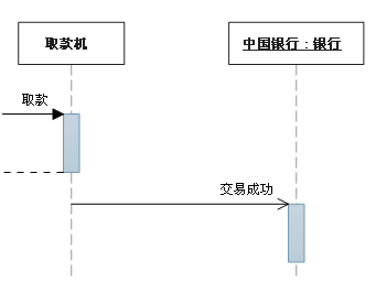
Messages are arrows from one object's lifeline to another object's lifeline. Their vertical order is the order in which the messages occur, from top to bottom.
Lifelines and messages
A lifeline can have an underlined name. The underline means the lifeline stands for a specific instance of a class rather than the class itself.
A synchronous message is one where the sender waits for the response before it continues.
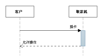
An asynchronous message does not make the sender wait before continuing.
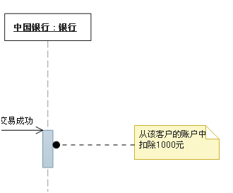
Notes and constraints are also part of the notation. A note is used for annotation. A constraint has a deliberately simple form: [Boolean Test].
Combined fragments
Combined fragments are how a sequence diagram handles conditions and ways of executing an interaction. They let the diagram show logic directly, defining special conditions and subprocesses for any part of any lifeline.
The common ones are:
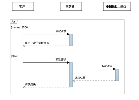
Alt (alternative) — a mutually exclusive choice between two or more message sequences, roughly the classic if..else.. Only one sequence happens on any occasion. Each fragment can have a guard indicating when it can run. The else guard marks the fragment to run when no other guard is true. If every guard is false and there is no else, no fragment runs.
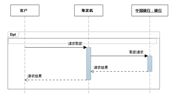
Opt (option) — a sequence that may or may not happen.
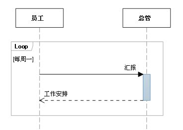
Loop — a fragment that repeats a set number of times. A guard can state the condition for repetition.
Par (parallel) — parallel processing.
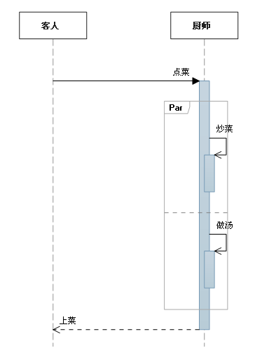
The table below lists the common fragment types.
<table> <thead> <tr> <th>Fragment type</th> <th>Name</th> <th>Meaning</th> </tr> </thead> <tbody> <tr> <td>Opt</td> <td>Option</td> <td>Contains a sequence that may or may not happen. A guard can specify when it happens.</td> </tr> <tr> <td>Alt</td> <td>Alternative</td> <td>Contains a list of fragments with alternative message sequences. Exactly one sequence happens on any occasion. Each fragment can have a guard. The else guard marks the fragment to run when no other guard is true. If all guards are false and there is no else, no fragment runs.</td> </tr> <tr> <td>Loop</td> <td>Loop</td> <td>The fragment repeats a number of times. A guard can indicate the repetition condition. A Loop fragment has 'Min' and 'Max' properties for the minimum and maximum repetitions; the default is unlimited.</td> </tr> <tr> <td>Break</td> <td>Break</td> <td>If this fragment executes, the rest of the sequence is abandoned. A guard can indicate the condition for the break.</td> </tr> <tr> <td>Par</td> <td>Parallel</td> <td>Parallel processing. Events in the fragment can interleave.</td> </tr> <tr> <td>Critical</td> <td>Critical</td> <td>Used inside Par or Seq fragments. Indicates that messages in this fragment must not interleave with other messages.</td> </tr> <tr> <td>Seq</td> <td>Weak order</td> <td>Has two or more operand fragments. Messages involving the same lifeline must occur in the fragment order. If messages involve different lifelines, messages from different fragments may interleave in parallel.</td> </tr> <tr> <td>Strict</td> <td>Strong order</td> <td>Has two or more operand fragments. These fragments must occur in the given order.</td> </tr> </tbody> </table>By default, a sequence diagram shows one possible series of messages. In a running system, other messages may occur that were not chosen for the diagram.
The following fragment types change that interpretation:
<table> <thead> <tr> <th>Fragment type</th> <th>Name</th> <th>Meaning</th> </tr> </thead> <tbody> <tr> <td>Consider</td> <td>Consider</td> <td>Specifies the list of messages this fragment describes. Other messages may occur in the running system but do not matter for this description. Enter the list in the 'Messages' property.</td> </tr> <tr> <td>Ignore</td> <td>Ignore</td> <td>Lists messages this fragment does not describe. These messages may occur in the running system but do not matter for this description. Enter the list in the 'Messages' property.</td> </tr> <tr> <td>Assert</td> <td>Assert</td> <td>The operand fragment specifies the only valid sequence. Usually used inside Consider or Ignore fragments.</td> </tr> <tr> <td>Neg</td> <td>Negative</td> <td>The sequence shown in this fragment must not occur. Usually used inside Consider or Ignore fragments.</td> </tr> </tbody> </table>Use case diagrams
A use case diagram describes relationships among users, requirements, and system function units. It shows a model of system functions as an external user can observe them. Its practical purpose is to help the development team understand functional requirements visually.
The elements include:
- Actor — a user, organization, or external system that interacts with the application or system. Drawn as a stick figure.

- Use case — an externally visible system function, describing a service the system provides. Drawn as an ellipse.
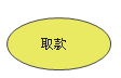
- Subsystem — shows a part of the system's functionality, specifically a closely related part.
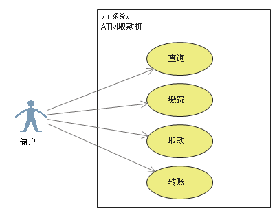
- Relationships — association, generalization, include, and extend.
 </td>
</tr>
<tr>
<td>Generalization</td>
<td>Relationship between actors or between use cases</td>
<td>
 </td>
</tr>
<tr>
<td>Include</td>
<td>Relationship between use cases</td>
<td>
 </td>
</tr>
<tr>
<td>Extend</td>
<td>Relationship between use cases</td>
<td>
 </td>
</tr>
</tbody>
</table>
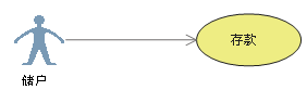
- Association — communication between an actor and a use case; either side can send or receive a message. The arrow points to the receiver.
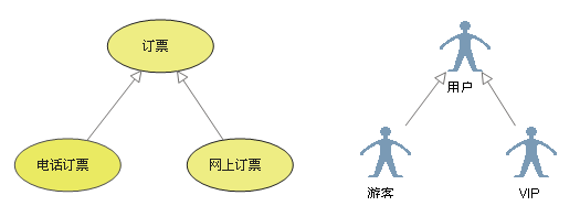
- Generalization (inheritance) — the usual inheritance idea. A child use case resembles its parent but shows more specific behavior. The child inherits all of the parent's structure, behavior, and relationships. It can use part of the parent's behavior or override it. The parent is usually abstract. The arrow points to the parent use case.
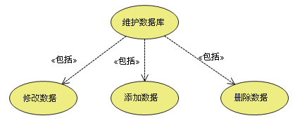
- Include — breaks the functionality represented by a more complex use case into smaller steps. The arrow points to the included function use case.
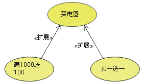
- Extend — extends a use case's functionality, effectively giving the base use case an additional function. The arrow points to the base use case.
- Dependency — not one of the four standard relationships above, but added in Visual Studio 2010 use case model diagrams. It is drawn as a dashed arrow, meaning the source use case depends on the target use case. The arrow points to the item depended on.
-
Artifact — a use case diagram is meant to help people understand functional requirements, but in practice not many people can read it well. Sometimes communicating with users through Excel is stronger than using a use case diagram. Visual Studio 2010 introduced the artifact element so developers can link an ordinary document into the diagram. A use case depends on the artifact through a dependency; then the artifact's Hyperlink property is set to the document. Double-clicking the artifact in the use case diagram opens the associated document.
-
Comment — comments are available for annotation.
Include, extend, and generalization
The differences are worth keeping straight:
- Conditionality: a child use case in a generalization and an included use case in an include happen unconditionally. An extension use case in an extend happens conditionally.
- Directness: a child use case in a generalization and an extension use case in an extend provide direct service to the actor. An included use case in an include provides indirect service.
- Extend: the extension use case does not contain the base use case's content, and the base use case does not contain the extension's content.
- Inheritance: the child use case contains all of the base use case's content and its relationships with other use cases or actors.
Where the notation gets awkward
Use case diagrams still feel immature. They do not express system requirements well, and users without a UML background can hardly tell what the drawing means. Include and extend even use the same arrow symbol; only a text label above the arrow distinguishes them. Translate that label into another language and the meaning is nearly lost. The direction of the extend arrow is also hard to justify at first glance: why point to the base use case instead of the extension use case?
The artifact element added in Visual Studio 2010 is a useful innovation because it can associate Word or Excel documents with a use case diagram. But why not integrate that function directly into the use case? Double-clicking a use case to open a document would be easier to understand than adding another element whose only job is to provide a link.
Because a use case diagram alone rarely makes functional requirements clear, development teams commonly use a use case description table to supplement use cases that are hard to express visually.